Agv Battery Charger: The Ultimate 2025 Sourcing Guide
Introduction: Navigating the Global Market for AGV Battery Chargers
AGV fleets live or die by their charging infrastructure. The wrong charger curve, poor communication, or a misaligned regional compliance plan will create chronic downtime and safety exposure. This guide helps USA and Europe buyers choose and implement AGV battery chargers that deliver predictable uptime while fitting local codes and grid realities.
First, you’ll define fit-to-chemistry profiles across Li-ion variants. The chargers must support customized charging curves—programmable per chemistry and application—so a one-size-fits-all approach underperforms. Reprogrammable curves in the field simplify commissioning and lifecycle optimization.
Next, selecting the correct form factor matters. Onboard chargers increase route flexibility and reduce manual handling; stationary systems scale capacity and support opportunity fast charging. For larger fleets, high-power solutions (up to 100 kW) enable fast turnarounds and multi-shift coverage without overstressing the grid.
Communication and integration decide system behavior. Ensure CAN bus, Ethernet, or radio integration to coordinate AGV states, interlocks, and fault handling; optional I/O cards broaden compatibility. Centralized fleet management enables remote monitoring, automated data capture, and user-defined alerts—critical for proactive maintenance and compliance reporting.
Finally, align with regional requirements. Expect to meet North American and European safety and EMC standards, as well as grid code considerations; documentation, labeling, and installation practices must match market-specific expectations.
Illustrative Image (Source: Google Search)
By combining chemistry-aware charging, scalable power, robust communications, and regional compliance, you’ll cut losses from mismatched chargers and create a resilient charging backbone.
Top 10 Agv Battery Charger Manufacturers & Suppliers List
1. Top 10 Global AGV Battery Manufacturers – HIITIO
Domain: hiitio.com
Registered: 2022 (3 years)
Introduction: Top 10 Global AGV Battery Manufacturers · 1. HIITIO · 2. CATL · 3. BYD · 4. CALB · 5. EVE Energy · 6. Lishen · 7. Gotion · 8. Samsung SDI….
Illustrative Image (Source: Google Search)
2. AGV battery & battery charger – Charging made right
Domain: micropower-group.com
Registered: 2015 (10 years)
Introduction: Micropower supplies the AGV industry with our field proven, high quality battery chargers as onboard or stationary units with capacities up to 100 kW….
3. 2025 10 Leading AGV Battery Charger Factory in the world – Blog
Domain: yewycharger.com
Registered: 2021 (4 years)
Introduction: XP Power is a leading provider of power solutions. Their AGV battery chargers are designed to be reliable, efficient, and easy to use. Features ……
4. Best 3 AGV Battery Manufacturers 2024
Domain: manlybattery.com
Registered: 2011 (14 years)
Introduction: This article explores the best AGV battery manufacturers, focusing on their production capabilities, product offerings, and commitment to quality….
5. Top 10 AGV Brands Driving Smart Logistics In 2025 – BSLBATT

Domain: bslbatt.com
Registered: 2020 (5 years)
Introduction: From global giants like KUKA and ABB to innovative players like Geek+ and Quicktron, these AGV manufacturers are driving the future of smart ……

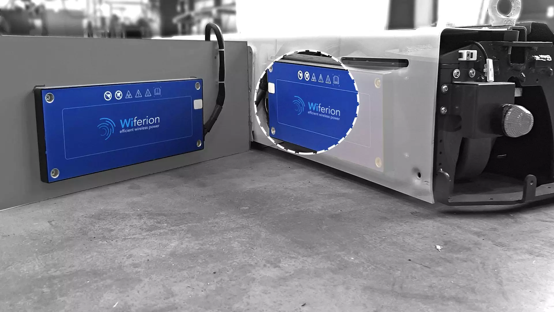
Illustrative Image (Source: Google Search)
6. AGV Wireless Charging: Manufacturers? Cost? Advantages?
Domain: agvnetwork.com
Registered: 2018 (7 years)
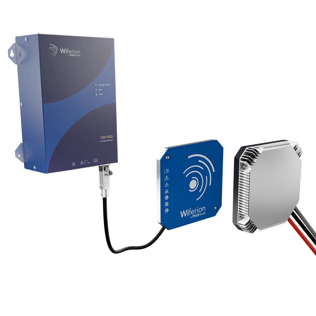
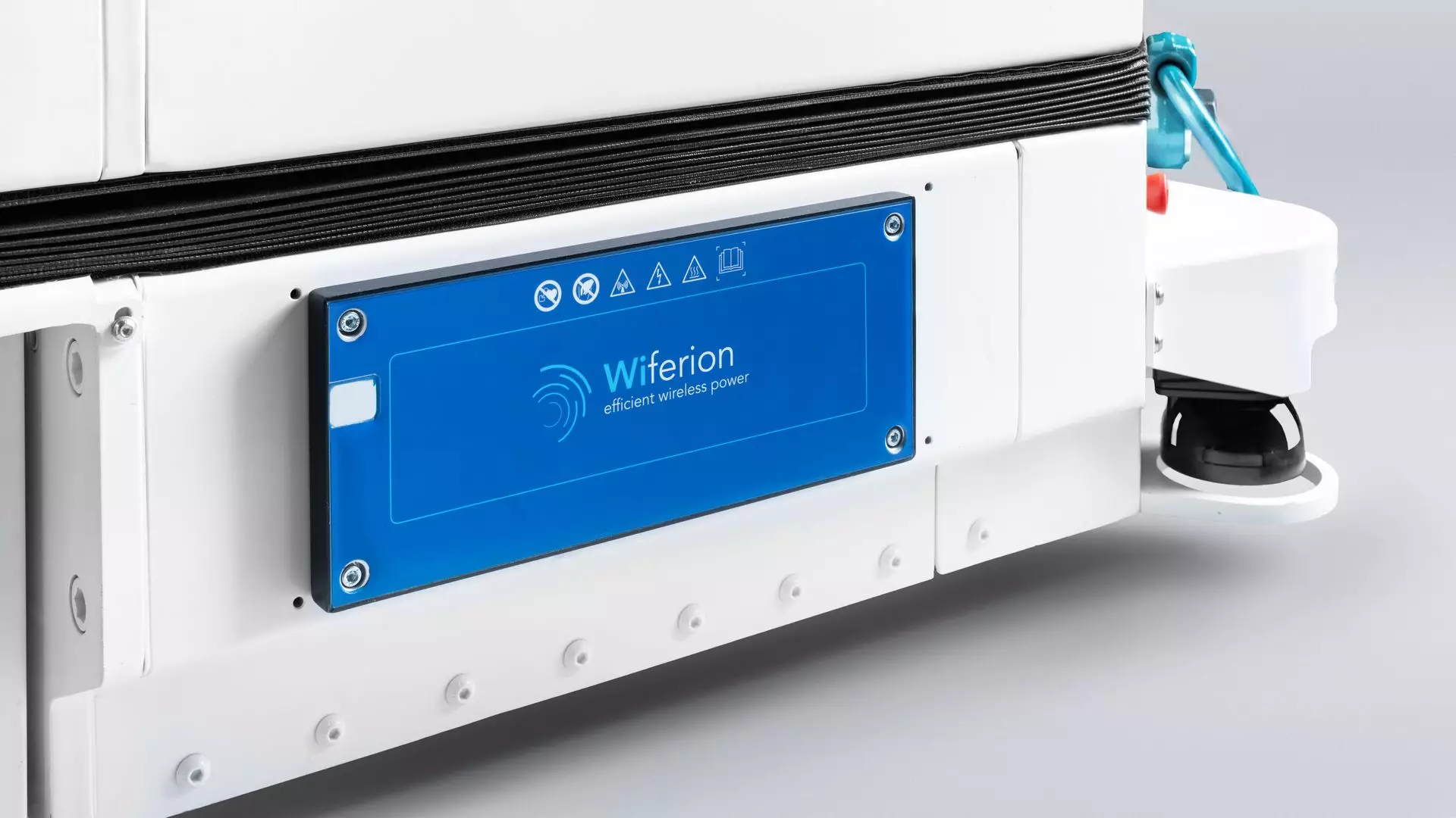
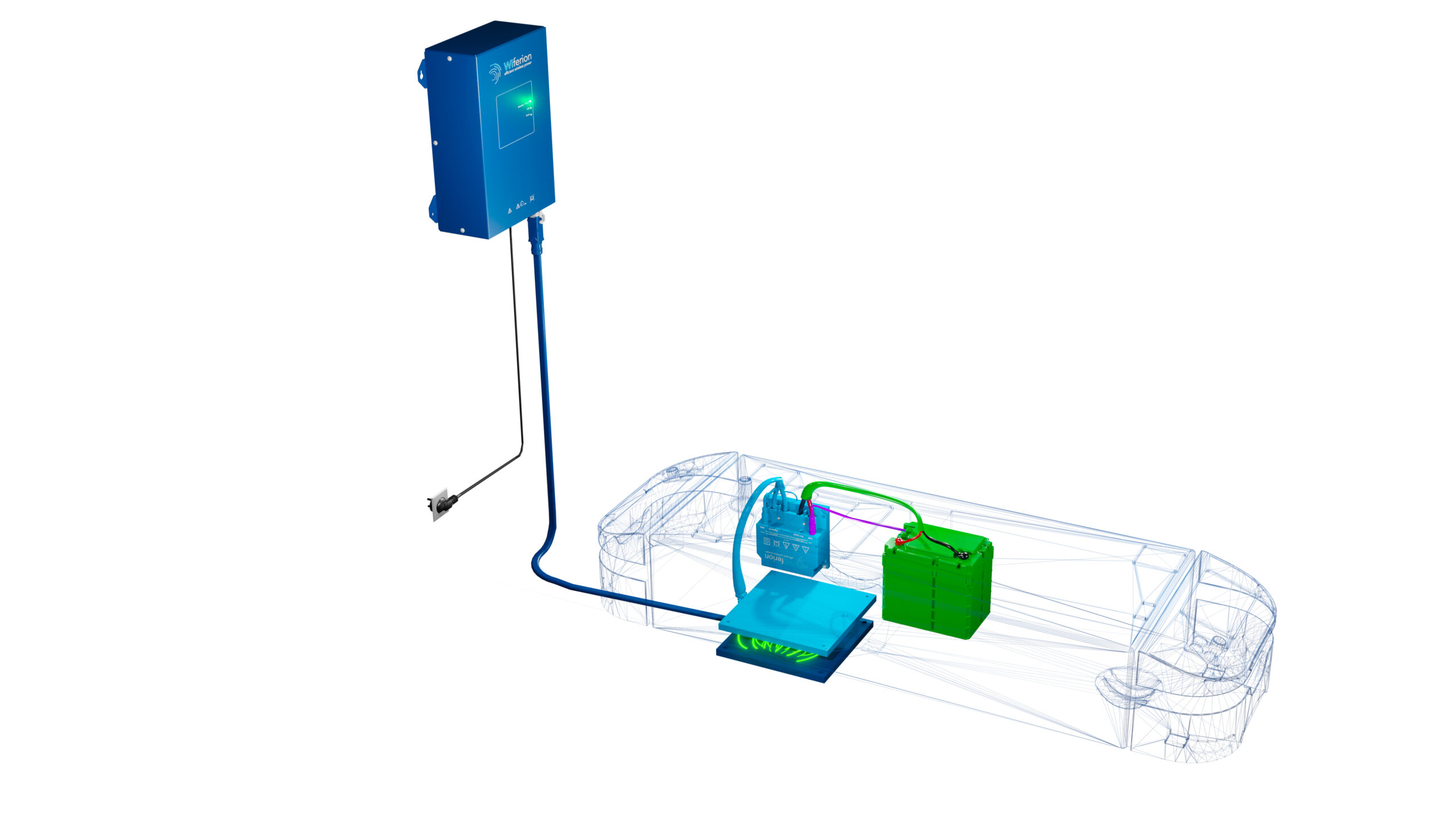
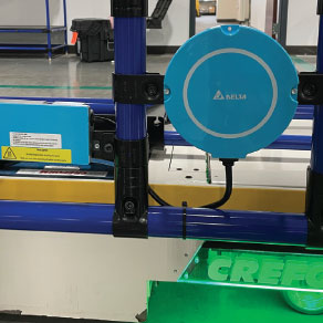
Introduction: The main AGV Wireless Charging Systems manufacturers are: Wiferion. B&PLUS. Buzzard by Multipowr. CaPow. Daihen. Delta Energy Systems. Enersys. WiBotic ……
7. Aisun – AiPower New Energy Technology Co., Ltd.
Domain: evaisun.net
Registered: 2023 (2 years)
Introduction: Aisun is a Leading EV Charging Solutions Brand Developed by Aipower, offering high quality electric vehicle charging station, forklift charger, AGV charger….
8. Versatile and customisable All-in-one intelligent Agv charger

Domain: gdtitanspower.com
Registered: 2022 (3 years)
Introduction: Rating 5.0 (99) Discover a versatile and customisable All-in-one intelligent Agv charger. Choose the perfect solution for your needs. Shop now for the best options!…
9. China 24V 48V AGV Battery Charger Suppliers, Manufacturers
Domain: summitcharger.com
Registered: 2021 (4 years)
Introduction: We’re well-known as one of the leading 24v 48v agv battery charger manufacturers and suppliers in China. Please rest assured to wholesale high quality 24v ……
Illustrative Image (Source: Google Search)
Understanding agv battery charger Types and Variations
Understanding AGV Battery Charger Types and Variations
AGV battery charging systems vary by installation method, communication protocols, charging speed, and power capacity. Selecting the right configuration ensures optimal fleet performance, compliance with safety standards, and seamless integration with existing automation infrastructure.
Charger Type Comparison
| Type | Features | Applications | Pros/Cons |
|---|---|---|---|
| Onboard Chargers | Integrated into AGV chassis, vehicle-mounted, CAN bus/Ethernet/Radio communication, I/O card options | Autonomous warehouses, manufacturing lines, high-mobility applications | Pros: Full mobility, automatic opportunistic charging Cons: Weight restrictions, limited power capacity, higher vehicle maintenance |
| Stationary Chargers | Fixed-location installation, higher power capacity (up to 100kW), conventional/fast charging, customizable charging curves | Ports, distribution centers, industrial yards | Pros: High power output, fast charging, lower vehicle costs Cons: Stationary operation, requires infrastructure planning |
| Conventional Chargers | Standard charging curves, programmed for specific battery chemistries, field-reprogrammable parameters | Standard AGV operations, cost-sensitive applications | Pros: Proven reliability, simpler setup, lower cost Cons: Longer charging times, limited flexibility |
| Fast Chargers | Rapid charging capability, high current delivery, automatic data transfer and analysis | High-utilization fleets, 24/7 operations, critical applications | Pros: Minimal downtime, increased productivity, remote monitoring Cons: Higher initial cost, potential battery stress, thermal management requirements |
Onboard Chargers
Onboard chargers integrate directly into the AGV chassis, enabling autonomous charging without human intervention. These units communicate through industry-standard protocols—CAN bus for vehicle integration, Ethernet for high-speed data transfer, or radio for wireless connectivity. Field technicians can reprogram charging parameters through the user interface to accommodate different battery chemistries or operational requirements.
Key applications: Autonomous mobile robots (AMRs) in warehouses, manufacturing assembly lines requiring continuous mobility, and facilities where AGVs operate across multiple charging zones. The integrated design supports opportunistic charging at waypoints and reduces infrastructure costs.
Considerations: Power capacity is limited by vehicle weight and space constraints. Maintenance requires access to onboard components, potentially increasing service complexity. Thermal management becomes critical in confined vehicle compartments.
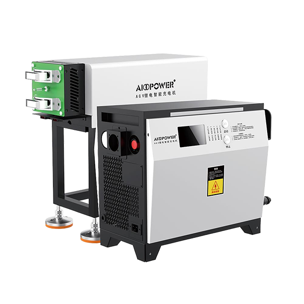
Illustrative Image (Source: Google Search)
Stationary Chargers
Stationary chargers provide high-capacity charging (up to 100kW) in fixed locations, supporting conventional and fast charging modes. These systems deliver customizable charging curves programmed according to battery specifications and can be reconfigured by service technicians when battery chemistries change.
Key applications: Port operations with high-throughput AGV fleets, large-scale distribution centers requiring rapid turnaround, and industrial environments where vehicles operate on defined routes between charging stations. Stationary installations enable centralized monitoring and easier maintenance access.
Considerations: Infrastructure planning and installation costs are higher. AGV mobility is limited to charging station proximity. However, these units offer superior charging performance and fleet management capabilities.
Conventional Chargers
Conventional chargers implement standardized charging curves optimized for specific battery chemistries, including lithium-ion configurations commonly used in AGV applications. Parameters are factory-set according to customer specifications but remain field-reprogrammable, allowing adaptation to changing operational requirements without replacement.
Illustrative Image (Source: Google Search)
Key applications: Standard industrial AGV operations, cost-sensitive deployments, and applications where extended charging times are acceptable. These units suit facilities with predictable charging windows and moderate utilization requirements.
Considerations: While offering proven reliability and lower acquisition costs, charging times are longer than fast-charging alternatives. Battery utilization may be suboptimal for high-demand applications requiring rapid turnaround.
Fast Chargers
Fast chargers deliver high-current charging to minimize vehicle downtime and maximize fleet productivity. These systems integrate with fleet management platforms for remote monitoring, automated data transfer, and real-time performance analysis. Automated alerts based on custom settings enable proactive maintenance and operational optimization.
Key applications: 24/7 operations requiring minimal downtime, high-utilization fleets in e-commerce fulfillment, and critical manufacturing processes where AGV availability directly impacts production schedules. Fast charging enables opportunity charging during brief operational pauses.
Considerations: Initial investment is higher, and battery thermal management becomes critical to prevent degradation. Fast charging may reduce battery lifespan compared to conventional charging methods, requiring careful balance between productivity gains and total cost of ownership.
System Integration Considerations
AGV charging solutions must integrate seamlessly with existing automation infrastructure. Communication protocols (CAN bus, Ethernet, radio) enable coordination with warehouse management systems, production control systems, and fleet management platforms. I/O card configurations extend compatibility with legacy equipment and custom automation interfaces.
Fleet management systems provide centralized monitoring, data analytics, and automated reporting. Remote access capabilities enable troubleshooting and parameter adjustments without on-site intervention, reducing maintenance costs and operational disruption. Automatic data transfer supports compliance reporting and performance optimization initiatives.
Selection criteria should prioritize compatibility with existing infrastructure, scalability for fleet expansion, and total cost of ownership including maintenance, energy costs, and battery replacement cycles. Field-proven solutions with proven track records in similar industrial environments minimize implementation risk.
Illustrative Image (Source: Google Search)
Key Industrial Applications of agv battery charger
Key Industrial Applications of AGV Battery Charger
Below is a concise overview of where AGV battery chargers make a measurable impact across major industrial segments in the USA and Europe. Applications are supported by customized charging curves, high-power charging, and field-proven communication and fleet management.
| Industry | Typical AGV Application | Why the Charger Matters (Supported Capability) |
|---|---|---|
| Warehousing & E-commerce | Pallet transport, goods-to-person, cross-dock transfers; opportunity charging during dwell | Customized curves per Li‑ion module maintain health under high duty cycles; onboard/stationary fast charging up to 100 kW with CAN/Ethernet/radio integration reduces missed opportunities; Fleet Management enables remote supervision and automated alerts to secure uptime. |
| Manufacturing & Electronics | Line-side kanban and coil transport; intralogistics for assembly cells; frequent opportunistic top‑ups | Field‑reprogrammable charging curves adapt to battery chemistry and cell configuration; robust I/O, CAN, and Ethernet link the charger to WMS/MES for deterministic charging windows; remote diagnostics minimize planned and unplanned downtime. |
| Automotive & Mobility | Body‑in‑white (BIW), powertrain and stamping intralogistics; tow/tugger trains | High‑power fast charging with duty-cycle-specific curves shortens dwell time; mixed chemistry support reduces spares complexity; CAN/Ethernet ensures AGV‑charger coordination under line‑stop conditions; radio options support retrofits without cabling. |
| Food, Beverage & Packaging | Cold‑chain and washdown zones; high‑speed conveyor support; pallet transport | IP‑rated onboard and stationary options support hygienic environments; rapid opportunity charging preserves energy and runtime under tight schedules; remote data and alerts identify thermal or charging anomalies before failures. |
| Pharmaceuticals & Cosmetics | Cleanroom AGVs for material movement; tray and tote handling; GMP‑aligned operations | Customized charging curves protect cells under controlled conditions; Fleet Management logs charger events for traceability; secure remote access enables rapid validation and safe service interventions without compromising cleanroom status. |
| Ports, Rail & Heavy Logistics | Terminal tractors, straddle carriers, rail shunting; high‑energy shuttle loops | Fast opportunity charging during port dwell and rail turnaround maximizes cycle count; 100 kW conventional/fast charging maintains state‑of‑ready; CAN/Ethernet radio integration enables coordination with terminal operations and safety systems. |
How to select the right charger
Use a structured approach to match the AGV’s mission and battery to the charger:
– Define power and time window: calculate peak power and charge time per duty cycle.
– Confirm chemistry and modules: select customized curves to match Li‑ion configuration and avoid aging from incorrect parameters.
– Choose onboard or stationary: favor onboard for opportunity charging at the work station; use stationary for high‑throughput depots and multi‑shift fleets.
– Integrate communications: specify CAN, Ethernet, or radio as required by the AGV control system; add I/O for external interlocks and triggers.
– Enable remote oversight: deploy Fleet Management for automatic data collection, health metrics, and alerts tailored to your SOPs.
By tuning the charging curve to the battery chemistry and integrating the charger into your AGV and fleet systems, you protect battery life, keep vehicles available when needed, and reduce unplanned downtime.
3 Common User Pain Points for ‘agv battery charger’ & Their Solutions
3 Common User Pain Points for ‘AGV Battery Charger’ & Their Solutions
Pain Point 1: Charger–Battery Mismatch and Premature Degradation
- Scenario
- A mixed-fleet of AGVs uses Li‑ion packs with different capacities and chemistries. Chargers are left at defaults or outdated profiles.
- Problem
- Incorrect charging curves (CC/CV) cause over/under‑charging, high voltage stress, and accelerated capacity loss. Downtime rises as batteries age faster.
- Solution
- Use AGV battery chargers with customizable charging curves tailored per battery chemistry and capacity. Set parameters at installation and re‑program in the field to match newer packs or changing duty cycles. Choose chargers designed for conventional or fast charging to balance runtime and lifespan.
Pain Point 2: Integration Gaps and Limited Control
- Scenario
- Chargers need to communicate with the AGV controller, safety interlocks, and building systems.
- Problem
- Legacy chargers lack native interfaces or use proprietary protocols; I/O wiring is clunky; status/events are not visible to higher-level systems, causing coordination failures.
- Solution
- Deploy chargers with built-in CAN bus, Ethernet, and radio connectivity, plus optional I/O cards for interlocks and external signals. Enable bi‑directional status, commands, and coordinated charging logic via open communication. Select onboard or stationary models up to 100 kW, with 24/7/365 or opportunity (fast) charging strategies tailored to the process.
Pain Point 3: Limited Visibility Leading to Unplanned Downtime
- Scenario
- Operations rely on reactive maintenance; chargers and batteries are treated as “black boxes.”
- Problem
- No real-time state-of-charge, health, or fault data; failures are discovered too late; productivity and on-time rates suffer.
- Solution
- Connect chargers and batteries to a Fleet Management System for remote monitoring, automated data transfer, and alerts tied to your thresholds. Use dashboards for daily operations and trending, then act on alerts before faults impact throughput.
Strategic Material Selection Guide for agv battery charger
Strategic Material Selection Guide for AGV Battery Charger
Objectives
- Maximize reliability in 24/7 operations and harsh environments
- Ensure thermal performance while minimizing size and weight
- Meet EMI/EMC and safety requirements in USA and Europe
- Simplify manufacturability, field serviceability, and compliance
System-level considerations
- Power topology: conventional or fast charging up to 100 kW
- Cooling method: convection, forced air, liquid cold-plate
- Form factor: onboard vs stationary; space constraints and mounting
- Integration: CAN bus, Ethernet, radio; I/O for auxiliary functions
- Environment: temperature, vibration, dust/moisture, chemicals
Material choices by component
Enclosure/structural
– Aluminum extrusions: excellent strength-to-weight, good EMI shielding, natural anodic corrosion resistance. Preferred for 15–100 kW units and onboard installations.
– Steel: robust, low cost, heavy; used where structural rigidity trumps weight. Powder-coated for corrosion; consider galvanic isolation from aluminum busbars.
– Stainless steel (304/316): best corrosion resistance; use in food/beverage, outdoor, chemical exposure. Higher cost and weight limit widespread use.
– Plastic (PC/ABS, ASA): lightweight, molded features, dielectric isolation; limited to low-power stationary chargers or covers. Needs flame ratings (UL 94 V-0), EMI coating if used as primary enclosure.
Illustrative Image (Source: Google Search)
Power electronics
– Copper (busbars, laminates): low resistance, high current carrying; requires plating (tin/nickel/silver) for solderability and anti-oxidation. Avoid zinc for high-current DC due to creep/corrosion.
– Aluminum busbars: lighter, lower cost at high power density, but higher resistance. Use nickel/tin plating; validate thermal expansion with copper connections. Fit for liquid-cooled or larger footprints.
– Semiconductors: Si for mainstream topologies; SiC for high-frequency, compact, high-efficiency fast charging (reduced switching losses). Ensure compatible gate drivers and thermal interfaces.
– Magnetic components: ferrite cores (low losses) vs iron powder (higher saturation, robust). Select based on switching frequency and temperature.
Thermal management
– Aluminum cold plates: extruded, machined, or friction-stir-welded; excellent for liquid-cooled AGV chargers.
– Phase-change materials (PCM): buffer thermal transients during fast charge; pair with liquid or forced-air for sustained loads.
– Thermal interface materials (TIMs): graphite sheets for spreaders, silicone/PTFE gap pads for isolation, thermal greases/pastes for interface pressure control.
Insulation and isolation
– FR-4 and polyimide PCBs for high-temperature areas; IPC Class 2/3 reliability for automotive-like service conditions.
– Ceramic substrates (DBC/DBA) for power modules: high thermal conductivity, excellent electrical isolation; higher cost, brittle.
Fastening and interface
– Stainless steel fasteners where corrosion resistance is needed; zinc-plated steel otherwise.
– Seals: EPDM (outdoor/weather), silicone (high temp), FKM (chemical resistance). Specify IP rating per IEC 60529 and consider cleaning solvents.
– Contact materials: copper-nickel-silver or gold plating for auxiliary connectors; tin plating for low-cost terminations; avoid bare copper in dynamic connectors.
Compliance anchors (USA/Europe)
- Safety: IEC/EN 62477-1 (power electronics) and applicable EMC (IEC/EN 61000 series). National deviations per market.
- Fire/flammability: UL 94 V-0 for polymer parts; NEC/CEC wiring and installation requirements for stationary chargers.
- EMI/EMC: Aluminum/steel enclosures act as Faraday cages; galvanic isolation between high and low voltage compartments; shielded harnesses for CAN/Ethernet where applicable.
- Environmental: REACh, RoHS; specify low-halogen laminates and solder; material declarations (IMDS for automotive-style supply).
Decision guidance
- Onboard, high-power, space-constrained: aluminum enclosure + SiC semiconductors + copper busbars + liquid cold-plate.
- Stationary, cost-sensitive: aluminum or steel enclosure + Si semiconductors + aluminum/copper mix + forced-air cooling.
- Harsh/chemical: stainless fasteners + stainless/aluminum enclosure as needed + FKM seals + corrosion-resistant plating.
- EMI-critical designs: thick steel enclosure or aluminum with conductive gaskets + cable shielding + careful grounding strategy.
Comparison table
| Material/Substrate | Typical use | Pros | Cons | Thermal/Mechanical traits | Weight considerations | Environmental/Compliance notes |
|---|---|---|---|---|---|---|
| Aluminum (enclosure, heat sinks, cold plates) | Structural, EMI shielding, cooling | High strength/weight, corrosion resistance, good thermal conductivity | Requires protection at cut edges, galvanic issues vs steel | High conductivity; extrusions/complex channels possible | Low to medium | REACh/RoHS compliant; anodized surface improves corrosion |
| Steel (enclosure, chassis) | Structural rigidity | Robust, low cost, excellent shielding | Heavy; corrosion unless coated | Moderate conductivity; robust impact resistance | Medium to high | Powder coat for corrosion; UL 94 applicable to coatings |
| Stainless steel (304/316) | Harsh/chemical environments | Best corrosion resistance; cleanable | High cost/weight; machining difficulty | Moderate conductivity; very robust | High | Meets food/chemical standards; specify finish |
| PC/ABS, ASA (plastics) | Small enclosures, covers | Lightweight; dielectric; moldable | Limited high-temp use; needs EMI treatment | Low thermal conductivity | Low | UL 94 V-0 flame ratings; requires conductive coating for EMI |
| Copper (busbars, laminates) | High-current DC paths | Lowest resistance; proven solderability | Cost; heavier than aluminum | High conductivity; stable mechanical properties | Medium to high | Plating: tin/nickel/silver; RoHS/lead-free requirements |
| Aluminum busbars | Power distribution in large chargers | Lightweight; lower cost | Higher resistance than copper; plating critical | Moderate conductivity; good for liquid-cooled designs | Low to medium | Nickel/tin plating to prevent creep/oxidation |
| Si (semiconductors) | Conventional topologies | Mature, cost-effective | Higher losses vs SiC | Standard thermal packages | N/A | Broad compliance; widely supported |
| SiC (semiconductors) | High-efficiency, fast charging | Higher frequency, lower losses, compact design | Higher cost; careful layout/EMI design | Better high-temp operation | N/A | Supports compact, lighter aluminum enclosures |
| FR-4 (PCB) | Control sections, low-voltage | Cost-effective; good insulation | Limited high-temp operation | Moderate thermal conductivity | Low | IPC Class 2/3; RoHS solder |
| Polyimide (PCB) | High-temp areas | Better thermal endurance | Higher cost | Slightly higher temp capability | Low | Use in hot zones near power stage |
| Ceramic substrate (DBC/DBA) | Power modules | Excellent thermal conductivity; electrical isolation | Brittle; cost | Very high thermal performance | Low | Solderable; often pre-packaged modules |
| EPDM (seals) | Outdoor/weather sealing | Good compression set; cost-effective | Limited high temp | N/A | N/A | IP-rated gaskets; outdoor compliance |
| Silicone (seals) | High-temp sealing | Wide temp range | Higher cost | N/A | N/A | Medical/industrial grades available |
| FKM (seals) | Chemical resistance | Solvent resistant | Temperature limitations vs silicone | N/A | N/A | Chemical plant applications |
| Stainless steel fasteners | Corrosion-prone zones | Corrosion resistance | Higher cost | N/A | Medium | Food/bev; marine; outdoor sites |
Next steps
- Validate by duty cycle and worst-case thermal simulation (conventional vs fast charging).
- Prototype thermal path and EMI/EMC before enclosure material lock-in.
- Specify plating, seal materials, and environmental ratings early to avoid redesign.
- Align procurement and compliance (UL/EN, NEC/CEC, REACh/RoHS) before pilot build.
In-depth Look: Manufacturing Processes and Quality Assurance for agv battery charger
In-depth Look: Manufacturing Processes and Quality Assurance for AGV Battery Charger
Overview
AGV battery chargers are high-reliability power conversion systems designed for demanding 24/7 operations. Manufacturing must balance precision, throughput, and traceability with rigorous quality assurance across Prep, Forming, Assembly, and QC stages. This section outlines typical process flows, testing, and certifications that underpin product consistency and safety in the USA and Europe.
Manufacturing Flow
| Stage | Objectives | Key Activities | Typical In-Process Controls |
|---|---|---|---|
| Prep (NPD & Supply) | Design-to-manufacture, component readiness, compliance | Component sourcing and qualification; PCB layout and DFM/DFT; specification of insulation class and safety margins; firmware release; material traceability | Approved BOM; RoHS/REACH compliance checks; DFM sign-off; First Article Inspection (FAI) |
| Forming (Mechanicals) | Enclosure, busbars, and assemblies | Sheet metal fabrication (laser cutting, CNC bending); powder coating; chassis assembly; busbar forming; sealing/gasketing; connector preparation | Dimensional inspection; adhesion/corrosion resistance; continuity and torque verification; finish quality audit |
| Assembly (Electrical) | Build and interconnects | Winding/transformer assembly; PCB population (SMT); THT soldering; component placement; wiring and busbar mating; connector crimping; heatsink and fan mounting; conformal coating | In-circuit test (ICT); visual inspection (AOI/AXI where applicable); partial discharge/hipot for HV modules; torque/securement checks |
| QC (Testing & Verification) | Functional, safety, and reliability validation | Functional tests (CV/CC/U-I curves), comms integration (CAN/Ethernet), safety checks (hipot, insulation, touch current), EMC pre-compliance, thermal/run-in, burn-in, safety reviews | Test coverage > 95%; traceability from serial to BOM/firmware; nonconformance (NCR) and CAPA processes; release to ship only after sign-offs |
Note: Exact equipment and parameters vary by model and capacity (up to ~100 kW), onboard vs. stationary, and thermal class (air/liquid cooling).
Field Programmable Charging Curves and Interfaces
- Factory-set charging curves aligned to battery chemistry (Li-ion, Lead-acid, NiMH) and AGV duty cycle; re-programmable on-site via user interface.
- Communications: CAN bus, Ethernet, and optional radio; I/O cards for system-level control; full integration with fleet management systems for remote diagnostics and data logging.
Quality Assurance and Standards
- Quality management: ISO 9001 (Quality Management Systems) across design, procurement, and manufacturing; process controls and continuous improvement.
- Safety and reliability:
- ISO 17050 (Conformity Assessment) and relevant IEC/EN safety standards depending on product class.
- ISO 13849-1 (Functional Safety) when safety functions (e.g., interlock, emergency stop integration) are implemented.
- ISO 6469 series for industrial battery safety where applicable.
- EMC and radio: Compliance to EU directives/standards (EMC/RED/RoHS/REACH) and US FCC/UL/NFPA equivalents where required.
- Environmental and robustness: Design for humidity, vibration, dust ingress; environmental testing per application severity.
USA and Europe Compliance (Illustrative)
- Regulatory alignment: CE marking and EU DoC; US FCC (emissions/immunity where applicable); OSHA/NFPA electrical safety practices in industrial environments.
- Certifications: UL/ETL for product safety where mandated; ISO certification records retained with audit trails.
- Documentation: Risk assessments, test reports, calibration records, and traceability to component lots and firmware versions.
Data and Connectivity
- Automatic data transfer and analysis; user-friendly dashboards; configurable alerts for charging anomalies and system health.
- Integration points: CAN/Ethernet with AGV controller; radio modules for wireless updates; external I/O for auxiliary interlocks and status signals.
Practical QC Outcomes
- Functional pass rate aligned to target yield (e.g., ≥ 98% on first test pass for mature builds).
- Field reliability supported by burn-in and accelerated testing; warranty-backed performance with documented incident logs and CAPA closure.
- Remote monitoring enables proactive maintenance, reducing unplanned downtime.
Process Checklist (Abbreviated)
- Prep: DFM/DFT complete; components qualified; firmware released.
- Forming: Dimensional tolerance met; coatings and sealing verified; torque spec applied.
- Assembly: ICT/AOI pass; insulation and partial discharge tests executed; wiring quality audit.
- QC: Functional curves validated; comms verified; safety/EMC tests recorded; documentation compiled; final release signed off.
This structured manufacturing and QA framework underpins the performance, safety, and longevity of AGV battery chargers in demanding industrial deployments.
Practical Sourcing Guide: A Step-by-Step Checklist for ‘agv battery charger’
Practical Sourcing Guide: A Step-by-Step Checklist for AGV Battery Charger
Use this checklist to reduce risk, speed up deployment, and align technical, commercial, and compliance decisions with your AGV program goals in the USA and Europe.
Illustrative Image (Source: Google Search)
- Deliverable at the end of this guide: a procurement-ready specification and a shortlist with two candidates for pilot.
Step 1 — Define AGV and duty profile
Key inputs (specify for each AGV model/line):
– Shifts per day, dwell time at charger, average and peak duty cycles
– Available window(s) for charging (opportunity vs. depot charging)
– Ambient and enclosure conditions (temperature, dust, vibration, washdown)
– Space constraints (onboard vs. stationary; mounting options)
Acceptance notes:
– Clear duty profile and available charging time determine power rating and fast-charging necessity.
– Use real operation logs if possible to capture peak/low periods.
Step 2 — Set charger form factor and power rating
Choose either onboard (embedded in AGV) or stationary (depot/floor charger), then set power class.
Power budgeting (use 20–30% headroom minimum):
– Conventional charging: 0.5–1.2C typical for Li-ion
– Fast/ opportunity charging: 1–3C within safety and battery warranty limits
Charger capability ranges to benchmark:
– Capacities up to 100 kW
– Onboard or stationary units, conventional and fast charging
Feature comparison:
| Criteria | Onboard charger | Stationary charger |
|---|---|---|
| Integration effort | Higher (space, thermal, EMC, safety interlocks) | Lower (fixed location) |
| Uptime/flexibility | High (in-vehicle charging, opportunistic) | High (parallel charging at depot) |
| Maintenance access | Limited (vehicle downtime for service) | Easy access for service |
| EMC/EMI burden | In-cabinet environment | Externalized |
| Cable management | None (park-and-plug optional) | Requires managed cables/ports |
| Typical power range | 5–30 kW common | 10–100 kW common |
Acceptance notes:
– Pick the form factor that best aligns with the vehicle’s duty cycle, safety architecture, and maintenance strategy.
– Confirm mechanical/thermal feasibility early to avoid late redesigns.
Step 3 — Ensure battery chemistry and charging curve compatibility
Confirm the charger can support your battery’s chemistry and required charging algorithm.
Illustrative Image (Source: Google Search)
Battery compatibility and settings:
| Battery type | Common use | Notes on charger settings |
|---|---|---|
| Li-ion (e.g., NMC, LFP) | AGV primary | Charger must support tailored CC/CV, I/U/ΔV parameters; ensure thermal monitoring integration |
| Lead-acid (flooded/AGM/GEL) | Legacy fleets | May be required to support legacy AGVs; confirm availability if needed |
| NiMH | Niche legacy | Confirm availability if required |
Key requirements:
– Customizable charging curves set at factory and field-reprogrammable via product interface by service technicians (for your environment).
– Charger parameters aligned to battery manufacturer datasheet (cutoff voltages, taper currents, thermal protection, time windows).
Acceptance notes:
– Obtain chemistry confirmation and parameter sheet from supplier before finalizing firmware.
– Lock in curve profiles per battery SKU to avoid cross-deployment errors.
Step 4 — Select communications and digital integration
Decide on control and data exchange method based on system architecture.
Illustrative Image (Source: Google Search)
Communication options:
– CAN bus, Ethernet, or radio connectivity between charger and AGV
– I/O cards available for versatile system integration (e.g., interlock signals, occupancy sensors)
– Fleet Management System (optional) to enable:
– Remote control and access to daily operations
– Automatic data transfer and analysis
– User-friendly interface and automated alerts based on your settings
Integration matrix:
| Integration need | Recommended path | When to use |
|---|---|---|
| Basic control (start/stop, status) | Digital I/O | Legacy AGV controllers or simple automation |
| Vehicle data (SoC, fault codes) | CAN bus | Moderate integration complexity; widely supported |
| High-speed data/logging | Ethernet | High data volume, fleet analytics, secure networks |
| Wireless orchestration | Radio | Dynamic charging zones, mobile fleets |
Acceptance notes:
– Define message and data requirements in the control specification (signals, baud rates, QoS, security policy).
– Test integration end-to-end in a lab before going live.
Step 5 — Address regulatory compliance and safety
Compliance must be verified at component and system levels (USA and Europe).
Illustrative Image (Source: Google Search)
Verification checklist:
| Topic | Requirement | Evidence to request |
|---|---|---|
| Product safety (USA) | UL recognition/listing for charger | UL file number, scope, conditions of acceptability |
| EMC (EU) | EMC Directive compliance (emissions/immunity) | Declaration of Conformity, test reports |
| Low voltage (EU) | LVD compliance | CE Declaration, safety test reports |
| Network security | Secure connectivity if networked | Documentation of access control, firmware update policies |
| Functional safety | If applicable (e.g., SIL), specify ASIL/SIL and verification | Safety case, SIL documentation, test evidence |
| Environment | IP rating, shock/vibration, hazardous location suitability | Datasheets, test certificates, operating environment specs |
Acceptance notes:
– Confirm UL/EMC/LVD certifications applicable to your model/options.
– Specify documentation packs and test reports in the RFP.
Step 6 — Specify thermal, EMC, and environmental robustness
Define the environmental profile for both stationary and onboard deployments.
Environmental requirements (specify ranges):
– Ambient operating temperature, humidity, and washdown/cleanroom expectations
– Thermal management: adequate airflow/cooling; de-rating at elevated temperature
– EMC/EMI immunity in industrial environments; cable routing and shielding plan
– IP rating for enclosure; cable entry sealing strategy
Illustrative Image (Source: Google Search)
Acceptance notes:
– Require derating curves and thermal test reports at or above your ambient extremes.
– Align cooling concept to your maintenance plan (filter cleaning, airflow paths).
Step 7 — Plan operations, serviceability, and reliability
Define how the charger is operated and maintained in your fleet.
Operational planning:
– User interface requirements (local/HMI/GUI) and remote operation via Fleet Management
– Alarms and events: thresholds, escalation paths, integration into your MES/SCADA
– Serviceability: access for diagnostics, field-reprogramming of charging curves via product interface
– Spares strategy: recommended spares list, firmware version control, rollback process
– Warranty and RMA: terms, remote triage windows, spare pools
Acceptance notes:
– Set uptime targets and MTBF/MTTR expectations; tie to KPI incentives where possible.
– Require service training and documentation access for your team.
Illustrative Image (Source: Google Search)
Step 8 — Quantify costs (TCO) and set commercial terms
Build a complete cost model aligned to your business case.
Cost breakdown (include in TCO):
– Capital: unit price per charger (by power class), shipping and installation materials
– Infrastructure: electrical upgrades, conduits, cable management, mounting hardware
– Integration: control engineering, testing, commissioning, acceptance
– Operations: energy costs (including power quality), firmware updates, fleet analytics subscription (if used)
– Maintenance: parts, on-site service, training refreshers, spares
– Compliance and logistics: certification documentation, local inspections, testing
Commercial terms to define:
– Lead times (standard and configured units), NRE for customization if applicable
– Spares coverage, RMA response targets, software updates, firmware support horizon
– Payment milestones (delivery, installation, acceptance), penalties for delays (if applicable)
– Onboarding/commissioning support, knowledge transfer, and documentation access
Acceptance notes:
– Require a total cost model, including energy, spares, and service for 3–5 years.
– Tie acceptance criteria to cost KPIs (e.g., cost per charge cycle).
Illustrative Image (Source: Google Search)
Step 9 — Verify vendor capability and deployment experience
Before shortlist, confirm capability to deliver and support.
Vendor qualification checklist:
| Capability | What to verify | Acceptable evidence |
|---|---|---|
| AGV market experience | Prior deployments with AGV OEMs and system integrators | Case studies, reference customers |
| Product portfolio | Field-proven charger range, flexible designs for AGV | Product datasheets, release notes |
| Integration | Communications (CAN/Ethernet/radio), I/O cards, fleet management | Integration guides, supported protocols |
| Field service | North America/Europe support footprint | Service center locations, response SLAs |
| Customization | Ability to tailor curves and system integration | Engineering questionnaire, customization examples |
| Documentation | Technical documentation, CE/UL scope | Datasheets, test reports, manuals |
Acceptance notes:
– Shortlist two suppliers for pilot with identical test plans and acceptance criteria.
Step 10 — Pilot, commission, and finalize acceptance
Run a structured pilot to de-risk scale-up.
Pilot plan checklist:
| Activity | Acceptance criteria | Owner | Timeline |
|---|---|---|---|
| Functional test | Charger delivers specified CV/CC curve within tolerance; no faults | Integration engineer | Week 1 |
| Integration test | CAN/Ethernet/radio and I/O signals operate per spec; alarm mapping verified | Controls engineer | Week 1–2 |
| Environmental test | Meets ambient/thermal spec in situ; derating behavior verified | Test engineer | Week 2 |
| Safety test | E-stop, interlock, door, and short-circuit protections validated | Safety engineer | Week 2 |
| Performance test | Meets dwell-time targets; energy per cycle accurate; fleet analytics data capture | Operations lead | Week 3 |
| Documentation | As-built, firmware versions, parameter sets (curves), certificates | Supplier | Week 3 |
| Go-live | On-site sign-off with KPI gate; spares and training confirmed | Project manager | End of Week 3 |
Acceptance notes:
– Freeze charging curves per battery SKU post pilot.
– Define KPI thresholds (uptime, charge time, energy accuracy) in the contract.
Quick comparison grid for “what good looks like”
Use this to evaluate candidates.
| Requirement | Micropower capability (for benchmarking) |
|---|---|
| Charging curves | Customized CC/CV curves set at factory and field-reprogrammable via product interface |
| Battery support | Supports several battery chemistries; Li-ion focus for AGV |
| Communications | CAN bus, Ethernet, radio; I/O cards available |
| Fleet management | Optional Fleet Management System with remote control, data analysis, and alerts |
| Charger form/power | Onboard or stationary, up to 100 kW; conventional and fast charging available |
| System integration | Field-proven portfolio with flexible designs and integration options |
| Support | Engineer-led system solutions; service technicians reprogram curves in the field |
Procurement-ready RFQ template (fill-in-the-blanks)
Copy this into your sourcing system.
- Form factor required: [Onboard / Stationary]
- Power rating (kW): [Value]
- Battery chemistry: [LFP / NMC / Other] + battery model/SKU: [Value]
- Desired charging profile: [Conventional / Fast] with parameters: [I_max, V_cutoff, taper rules]
- Communications: [CAN / Ethernet / Radio], required signals: [list]; I/O needs: [list]
- Environment: [Temp range, humidity, IP rating, EMC class]
- Compliance evidence required: [UL/EMC/LVD and other], hazardous area: [Yes/No]
- Operational controls: [Local HMI / Remote via Fleet Management], alarm mapping to: [MES/SCADA]
- Service model: [SLA targets], spares strategy, training required
- TCO period: [3–5 years], payment milestones and lead time targets
- Acceptance plan and KPI thresholds (to be pilot-validated)
- Required documentation pack: [datasheets, CE/UL, integration guides, test reports, manuals]
Deliverables sought:
– Detailed technical proposal with curve configurations
– Compliance documentation (UL/CE/LVD scope, test reports)
– Commercial quote including installation support and training
– Pilot timeline and project plan
Final note: If your application requires non-standard integration or charging behavior, ensure the supplier can deliver custom solutions. The best-fit charging system balances duty-cycle fit, integration simplicity, proven reliability, and compliant documentation for USA and Europe deployments.
Comprehensive Cost and Pricing Analysis for agv battery charger Sourcing
Comprehensive Cost and Pricing Analysis for AGV Battery Charger Sourcing
This section outlines how procurement and engineering teams in the USA and Europe should evaluate AGV battery charger total cost of ownership (TCO), price bands, and cost drivers across materials, labor, logistics, and compliance. It integrates sourcing levers that deliver savings without compromising quality or availability.
Price bands (typical, MSRP-equivalent ranges)
| Power profile | Rated power | Typical MSRP range | Notes |
|---|---|---|---|
| Conventional onboard | 3–10 kW | USD 7,000–18,000 / EUR 6,500–16,500 | Li-ion packs, AC supply, field-reprogrammable curves. |
| High-power onboard | 10–30 kW | USD 18,000–48,000 / EUR 16,500–44,000 | Active cooling, CAN bus, I/O expansion. |
| Stationary fast charge | 30–100 kW | USD 48,000–120,000 / EUR 44,000–110,000 | Heavy cooling, high connectivity (CAN, Ethernet, radio), safety I/O. |
Range variability depends on power level, cooling strategy, communications integration, enclosure/IP rating, certifications, and quantity. Expect tighter bands at mid-volume and above.
Illustrative Image (Source: Google Search)
Cost breakdown (typical share of FOB price)
| Cost driver | Materials | Labor | Logistics | Notes |
|---|---|---|---|---|
| Electronics and power stage (PFC/Inverter, HV isolation, busbars) | 45–58% | — | — | Power level, efficiency target, and topology drive cost. |
| Cooling (heat sinks, fans/pumps, thermal interface materials) | 6–12% | — | — | Active cooling increases component and assembly time. |
| Mechanical enclosure and harnesses | 8–14% | — | — | IP rating, materials, and cable harnessing complexity. |
| Software and system integration (CAN, Ethernet, radio, I/O cards) | 3–8% | — | — | Diagnostics, field programmability, remote control increase effort. |
| Assembly and wiring | — | 8–14% | — | Board-to-unit assembly and harness integration. |
| Validation and testing (burn-in, functional test) | — | 4–8% | — | Includes automated test coverage. |
| Compliance and certification (UL/CE, EMC, LVD, RoHS/WEEE readiness) | — | 2–5% | — | Pre-compliance testing can reduce surprises. |
| Packaging and freight | — | — | 2–6% | Charger weight/size and Incoterms (FOB/DAP/DDP). |
| QA and after-sales provisioning | — | 2–4% | — | Spare parts and field service support. |
| Warranty reserve | — | — | 1–3% | Longer warranties increase provisioning. |
| Overhead and margin (varies by region and supplier) | — | — | — | Supplier model and risk allocation drive this allocation. |
Indicative allocation sums to ~100% across categories; actual splits vary by vendor and configuration.
Materials (detailed drivers)
| Component | Cost impact | Typical drivers |
|---|---|---|
| Power electronics (PFC stage, high-frequency transformer, DC-DC stage) | High | Power level, efficiency class, switching frequency, component sourcing. |
| Thermal system (heat sinks, fans, pumps, TIMs) | Medium | Power density, duty cycle, ambient temperature, enclosure airflow. |
| HV components (connectors, HV relays, busbars, fuses) | Medium | Pack voltage, peak current, IP and environmental rating, UL/IEC compliance. |
| Connectivity modules (CAN transceiver, Ethernet PHY/radio) | Low–Medium | Protocol stack support, isolation, real-time performance. |
| I/O cards and safety relays | Low–Medium | Interlocks, E-stop chains, digital/analog I/O count. |
| Enclosure and cable harnessing | Medium | Size, material (aluminum vs steel), customization, cable management. |
| Firmware and diagnostics stack | Medium | Feature set, field reprogrammability, remote monitoring (Fleet Management). |
For Li-ion chemistries such as LFP or NMC, charger cost scales primarily with pack voltage, current limits, and thermal management, not chemistry itself. Customized charging curves are typically pre-configured and can be reprogrammed in the field—minimal cost impact once the firmware is modular.
Labor (engineering, integration, testing)
| Activity | Effort drivers | Cost drivers |
|---|---|---|
| Hardware design and firmware integration | Power level, topology, comms stack | Redundancy, performance tuning, safety functions. |
| Mechanical design and thermal validation | Active cooling, IP rating | Multiple iterations for noise/thermal limits. |
| System integration with AGV (CAN/Ethernet/radio) | Protocol variants, I/O mapping | Custom mapping and simulation tests. |
| Validation and testing (burn-in, EMC pre-compliance) | Test coverage and duration | More thorough testing reduces field failures. |
| Documentation and certification | Region (UL/CE), safety cases | Time for test plans and traceability. |
Field reprogrammability reduces field service costs by avoiding unit swaps for minor curve changes. Over the life of the project, the support plan matters more than upfront NRE.
Logistics (USA and Europe differences)
| Factor | USA | Europe | Cost implications |
|---|---|---|---|
| Certification path | UL recognition/marking (e.g., UL 1564) | CE (EMC 2014/30/EU, LVD 2014/35/EU) | Comparable testing effort; timing differs by lab capacity. |
| Standards alignment | NEC/CSA harmonization | EN standards | Minor documentation adjustments. |
| Tariffs and trade | Varies by origin (e.g., EU/US) | Varies by origin (e.g., US/EU) | Incoterms influence who pays. |
| VAT and invoicing | Sales/use tax state-dependent | VAT country-specific | Final landed price varies. |
| Logistics weight | >20 kg typical | >20 kg typical | Freight class, packaging, and insurance matter. |
| Transport cost | Sea for volume; air for spares | Sea for volume; air for spares | Faster air transport increases cost and reduces stock risk. |
| Compliance data | RoHS/WEEE, REACH documentation | RoHS/WEEE, REACH documentation | Administrative overhead similar across regions. |
Choose Incoterms wisely: FOB minimizes buyer complexity, DDP can help unify landed costs for large programs. Provide clear HS codes (typically 8504.40) and compliance data packs early to avoid delays.
Compliance and certification costs
| Region | Compliance scope | Cost drivers |
|---|---|---|
| USA | UL marking of units and use of recognized components; safety interlocks; EMC | Safety agency fees, test lab capacity, pre-compliance strategy. |
| Europe | CE marking (EMC and LVD); documentation; RoHS/WEEE readiness | Engineering time for EMC design, declaration, and file keeping. |
Plan pre-compliance testing to reduce full certification time. A repeatable platform design across regions lowers re-certification costs for variants.
Cost drivers by configuration
| Driver | Impact on cost | Notes |
|---|---|---|
| Power level (kW) | Linear–superlinear | Cooling and enclosure scale disproportionately above ~30 kW. |
| Cooling strategy | Medium–High | Active cooling adds BOM and assembly time; improves duty cycle. |
| Communication set (CAN, Ethernet, radio, I/O cards) | Low–Medium | More protocols and I/O increase hardware and integration time. |
| Safety interlocks and E-stop integration | Low–Medium | Hardwired safety typically required for stationary fast chargers. |
| Enclosure/IP rating | Medium | Higher IP rating increases material and testing complexity. |
| Ambient temperature and enclosure constraints | Medium | Derating affects sizing and BOM; thermal validation time. |
| Firmware features (custom curves, diagnostics, remote control) | Low–Medium | Platformized software reduces incremental cost per variant. |
| Warranty period | Medium | Longer warranties raise provisioning and risk reserves. |
Pricing logic and volume tiers
- Quantity-based tiers: expect discounts for multi-unit orders, especially above 100 units per year. The best pricing often requires multi-year programs or platform agreements.
- Standardization: using a common charger platform across fleets reduces per-unit cost by sharing non-recurring engineering and certification.
- Customization: bespoke curves and AGV-specific communications can be bundled at system level; minor tweaks carry modest incremental cost if the software is modular.
- Spares: remote-capable chargers reduce field swaps; invest in small pilot spares at key sites rather than large on-hand inventories.
Non-recurring engineering (NRE) and spares
| Item | Typical range | Notes |
|---|---|---|
| Platform setup (mechanical, thermal, firmware framework) | USD 60k–120k | Rewarded by lower per-unit prices in volume. |
| Compliance testing and certification prep | USD 20k–50k | Includes pre-compliance and agency fees. |
| Fleet integration and system testing | USD 30k–80k | CAN/Ethernet/radio integration and I/O mapping. |
| Pilot spares and tools | USD 10k–30k | Supports early deployment and validation. |
NRE costs are best amortized across multi-site deployments or multi-year volumes.
Risk and contract levers (USA vs Europe)
| Lever | USA | Europe | Impact |
|---|---|---|---|
| Warranty and RMA terms | State law varies | EU consumer/safety context | Define RMA windows and failure analysis responsibilities. |
| Escrow for firmware/IP | Common for software-heavy platforms | Common in critical infrastructure | Reduces vendor risk and supports continuity. |
| Service SLAs | Site-level response targets | Country/region-based | Tie response time to fleet uptime guarantees. |
| Obsolescence management | Component lifecycle plans | Component lifecycle plans | Long-term availability reduces replacements and cost. |
Procurement tips to save cost
- Consolidate volumes across sites and years; negotiate platform pricing rather than per-PO price.
- Standardize a charger platform with modular firmware; limit bespoke variants to documented differences only.
- Design for manufacturability: choose common housing sizes and standardized cable harnesses; reduce SKU proliferation.
- Thermal design discipline: specify realistic ambient limits and duty cycles; avoid oversizing that inflates cooling and material costs.
- Communication strategy: align on a baseline set (CAN + basic I/O); add Ethernet and radio only where value is clear.
- Compliance early: perform pre-compliance EMC testing and review safety interlocks before full certification.
- Freight optimization: ship full container loads where feasible; specify packaging that fits carrier dimensions and reduces damage risk.
- Logistics model: decide on Incoterms (FOB vs DDP) based on internal logistics capacity; DDP can simplify landed cost visibility.
- Spares with remote control: prefer remote diagnostics and reprogramming to minimize physical swaps; keep a small pool of pilot spares at high-criticality sites.
- Supplier selection: prioritize vendors with proven AGV experience, field-programmable chargers, and system-level connectivity; ask for a charger guide-aligned configuration that fits your battery’s chemistry and usage profile.
How Micropower-enabled features influence cost
- Customized charging curves set at factory and field-reprogrammable interfaces reduce service trips and accelerate commissioning.
- Communication via CAN bus, Ethernet, or radio, with I/O card expansion, standardizes integration and minimizes custom harnesses.
- Fleet Management connectivity for remote control and daily operations lowers downtime and support costs; the cost impact is modest relative to operational savings.
- Flexible Li-ion battery systems and a field-proven charger range support either integrated battery solutions or standalone units, simplifying sourcing and integration.
When to consider a custom solution
- Power levels above 100 kW or unique thermal envelopes.
- Non-standard voltage/current profiles not supported by standard firmware.
- Specialized safety or industrial protocols requiring I/O modifications.
- Envelope or mounting constraints that cannot be met by available housings.
In these cases, ask for a custom solution with a clear NRE plan, pre-compliance strategy, and a milestone-based cost schedule.
Checklist for USA and Europe sourcing
- Confirm chemistry (Li-ion), pack voltage, and current limits; validate thermal duty cycle.
- Select communications: CAN as baseline; add Ethernet or radio only as needed; define I/O interlocks.
- Specify enclosure/IP rating and ambient conditions; agree on cooling approach.
- Define compliance path: UL (USA) or CE (Europe) and test milestones.
- Align Incoterms, HS codes, and freight class; plan packaging for damage-free transit.
- Define warranty, RMA process, and field service support.
- Agree on firmware support (custom curves, diagnostics, Fleet Management connectivity).
- Set volume tiers and platform discounts; allocate NRE and pilot spares budgets.
- Establish risk controls: component lifecycle, obsolescence plan, and firmware escrow.
Final pricing logic
- Base price is driven by power level, thermal system, enclosure, communications, and compliance.
- Savings compound through platformization, volume consolidation, and modular firmware.
- Service strategy (remote control, field reprogrammability) reduces lifetime cost more than it adds to initial price.
- USA and Europe differ in certification and logistics specifics, but total cost drivers are consistent when the solution is designed with global standards in mind.
Alternatives Analysis: Comparing agv battery charger With Other Solutions
Alternatives Analysis: Comparing AGV Battery Charger With Other Solutions
Selection criteria
- Chemistries and configurable charging curves
- Integration and communication (CAN bus, Ethernet, radio)
- Field reprogramming and remote management
- Power and charging options (onboard/stationary, fast charge)
- Power capacity
- Safety and diagnostics (Fleet Management System, data/alerting)
- Deployment flexibility and typical applications
Comparison
| Feature / Option | AGV battery charger (Micropower example) | Conventional charger (non-integrated/lead-acid) | Simple Li‑ion charger (onboard/BMS limited integration) |
|---|---|---|---|
| Supported chemistries | Li‑ion; customizable curves set to specific chemistry in factory and re-programmable in field | Primarily lead‑acid; limited Li‑ion support; configurable parameters vary | Li‑ion only; chemistry presets; limited curve flexibility |
| Charging curves | Customized, field-reprogrammable via product interface | Fixed or limited presets | Fixed presets; limited customization |
| Communication | CAN bus, Ethernet, radio; add I/O cards for integration versatility | None or limited serial/I/O | CAN (often limited to basic BMS); limited Ethernet/radio |
| Remote management | Fleet Management System; data transfer, analysis, user-friendly interface, automated alerts | None | Basic telemetry; no centralized fleet management |
| Charger types | Onboard or stationary (up to 100 kW); conventional or fast charging | Stationary, lower power; fast charge uncommon | Onboard; power limited; fast charge optional |
| Maximum power | Up to 100 kW | Typically lower than 50 kW (application dependent) | Typically lower than 50 kW (application dependent) |
| Integration with AGV systems | Broad integration (battery chargers can communicate with AGV and other systems) | Minimal; direct wiring for basic control | Basic; requires additional integration work |
| Diagnostics and analytics | Remote data, automated alerts, analysis via Fleet Management | Basic charger LEDs; no remote insight | Basic BMS telemetry; limited analytics |
| Applications | High-volume, repetitive tasks in tough environments; automated/remote fleet operations | Materials handling with non-critical duty cycles | Li‑ion onboard use for light-duty AGVs |
Analysis
- Chemistry and curve control. AGV battery chargers designed for industrial automation support configurable charging curves across chemistries and allow re-programming in the field. Conventional chargers often target lead‑acid chemistry with fixed or limited presets, while simple Li‑ion chargers frequently rely on fixed presets, reducing flexibility when battery requirements or duty cycles change.
- Communication and system integration. Advanced AGV chargers offer CAN bus, Ethernet, and radio, with I/O cards for versatile integration. Conventional chargers typically lack communications or offer only basic I/O, which limits coordination with fleet controllers. Simple Li‑ion onboard chargers may provide limited CAN and BMS signaling but rarely support Ethernet, radio, or centralized fleet management.
- Fleet operations and maintenance. Remote management, automated data transfer, and analytics are standard with purpose-built AGV solutions. Conventional chargers do not support remote fleet control, and simple onboard chargers provide only basic telemetry, limiting preventive maintenance and operational insights.
- Deployment flexibility. Onboard and stationary options up to 100 kW, along with conventional and fast charging capabilities, suit diverse AGV environments and cycle demands. Conventional chargers are often stationary with lower power, and simple onboard chargers can be constrained by integration complexity and power limits.
- Suitability. Purpose-built AGV chargers best match high-volume, automated operations where communication, remote management, and flexible charging are critical. Conventional chargers remain viable for non-critical lead‑acid deployments. Simple Li‑ion chargers can work for light-duty onboard applications but typically require additional integration effort and offer limited remote visibility.
Recommendation: For production-scale AGV fleets operating in tough environments with integration, remote monitoring, and variable duty cycles, prioritize AGV-specific chargers with robust communications, customizable curves, and centralized fleet management. Validate local codes and standards (e.g., UL/EN/CE) before procurement; consult the charger guide or vendor team to confirm chemistry profiles, power class, and integration needs.
Essential Technical Properties and Trade Terminology for agv battery charger
Essential Technical Properties and Trade Terminology for AGV Battery Charger
Technical properties buyers should specify up front
- Application topology
- Onboard (vehicle-mounted): typically 3–30 kW, with conductive or inductive charging interfaces
- Stationary (depot/garage): typically 20–100 kW, fast charging; may be integrated with pantographs or custom couplers
- Electrical characteristics
- Nominal AC input: 208–480 V (±10% typical), single-phase or three-phase, 50/60 Hz
- Power at DC link: up to 100 kW (fast-charge), configurable to battery pack requirements
- DC output: V_OC range and I_max per charger; for high current, specify parallel units or modular topology if needed
- Output ripple/voltage stability: specify allowable ripple (e.g., <1% pk-pk) and regulation band for Li‑ion compatibility
- Power quality and conversion
- Efficiency: typical 94–96% for resonant PFC+LLC designs
- Power factor correction (PFC): active PFC typical (PF > 0.9 at nominal load)
- Input harmonics/surge: comply with IEEE 519 (recommended) and IEC 61000‑3‑2/‑3; surge protection built-in
- Charging control and chemistry support
- Charging curves: CC/CV/float/termination with chemistry-specific settings; factory-programmable, field re-programmable
- Battery chemistry: Li‑ion (e.g., NMC/LFP), NiMH/lead‑acid where supported
- Safety interlocks and approvals: ensure charger meets UL 1236 (US) and IEC/EN 60335‑2‑29 (EU) where applicable
- Integration and communication
- Protocols: CAN bus, Ethernet (TCP/IP), wireless radio; field bus support varies by model/series
- I/O options: 24 VDC logic, relays, analog signals; for AGV docking and sequence control
- Cybersecurity: authenticated remote access (e.g., TLS/SSH), user roles; firmware update control
- Thermal and environmental
- Cooling: convective, force‑air, or liquid; derating above typical 40–45°C; IP rating varies by series
- Enclosure and footprint: compact onboard vs larger stationary footprint with heatsinks/fans
- Noise: specify acceptable acoustic limits; use soft‑switching for high‑current applications where needed
- EMC, safety, and compliance (region‑specific)
- US/Canada: UL/ETL listing for safety; EMC per 47 CFR Part 15 Class A; consider NEC/CEC installation context
- EU/UK: CE/UKCA marking; LVD (2014/35/EU), EMC (2014/30/EU), RoHS (2011/65/EU), WEEE (2012/19/EU)
- Service and diagnostics
- Fault logging, trend analysis, and remote monitoring through a fleet management system
- Field re-programming via product interface (per source)
- Maintenance access points, self‑tests, and spare parts
Comparison: Onboard vs stationary AGV chargers
| Parameter | Onboard charger | Stationary charger |
|---|---|---|
| Typical power | 3–30 kW | 20–100 kW |
| Typical input | 208–480 V, single/three‑phase | 400–480 V, three‑phase preferred |
| Cooling | Convective/forced‑air | Forced‑air/liquid common at high power |
| Typical use | Opportunity/vehicle‑side charging | Depot/fast charging |
| Integration | CAN/IO for vehicle control | CAN/Ethernet; often paired with AGV docking control |
| Pros | No mating connector to maintain; simple AGV integration | High throughput; scalable power per bay |
| Cons | Space constraints; thermal derating in vehicle | Requires physical connection or pantograph; higher installation complexity |
Trade terminology frequently used in RFQs and purchase orders
| Term | Definition / Note |
|---|---|
| MOQ (Minimum Order Quantity) | Lowest quantity accepted per purchase order; requestable from OEM. |
| OEM (Original Equipment Manufacturer) | Manufacturer producing the charger and/or integrating into AGV system. |
| ODM (Original Design Manufacturer) | OEM that can redesign hardware/firmware; useful for custom integrations. |
| Private Label/White Label | Rebranded hardware/software supplied under buyer’s brand. |
| Customization | Charger or firmware changes for curves, I/O, enclosure, branding, or protocol tuning. |
| Lead time | Time from PO to shipment; typically quoted ex‑works. |
| Availability | Stock vs made‑to‑order; confirm current lead time in RFQ. |
| Ex‑works / Incoterms (FOB, CIF, DDP) | Delivery responsibility per Incoterms; specify at PO stage. |
| Warranty | Period, coverage, exclusions; specify RMA process and replacement vs repair. |
| Spare parts list | Critical components for maintenance; confirm availability window. |
| PM contract (Preventive Maintenance) | Scheduled checks and firmware updates; define annual scope and hours. |
| Repair turnaround (RMA) | Out‑of‑box timeframe; request target SLAs. |
| Firmware version control | Release notes, rollback policy, tested versions per battery chemistry. |
| Certification | Safety (UL/IEC/EN), EMC (EU/US), and product markings. |
| Declaration of Conformity (DoC) | EU documentation confirming compliance. |
| Test/quality documentation | FAT (Factory Acceptance Test), QA plan, material traceability. |
| Calibration certificate | Required annually for certain models; specify if needed. |
| Packaging/handling | Shock/vibration rated for transport; compliance with ISTA if relevant. |
| Documentation | Operator manual, service manual, wiring diagrams, safety labeling. |
| Compliance | RoHS, WEEE, China RoHS; EU battery regulation for battery‑integrated systems. |
| Customs | HS code, country of origin, preference certificate if applicable. |
| Payment terms | Net 30/60/90, proforma vs open account, deposits. |
| Non‑disclosure agreement (NDA) | Mandatory before sharing technical drawings or custom specs. |
| Field service | Onsite support during commissioning; clarify travel and labor rates. |
Best practices when requesting a quote
- Provide battery pack specifics: V_OC min/max, A·h, C‑rate, chemistry, recommended CV voltage, current limits, and thermal limits.
- Define the charger environment: ambient temperature, enclosure constraints, EMC zone, and safety rating expectations.
- Specify the AGV interface: required protocols, docking sequence (precharge/contactors), and any I/O interlock logic.
- State compliance requirements: country‑specific (UL/ETL for US/CA; CE/UKCA for EU/UK), and customer audit needs (FAT, QMS).
- Define delivery terms and service plan: Incoterms, lead time, warranty, PM coverage, and remote monitoring access.
Note: Always confirm model‑specific features (protocols, ratings, and certifications) against the current OEM datasheet.
Navigating Market Dynamics and Sourcing Trends in the agv battery charger Sector
Navigating Market Dynamics and Sourcing Trends in the AGV Battery Charger Sector
What is shaping buyer behavior across USA and Europe? Demand is driven by continuous operations, safety compliance, and cost predictability. Buyers expect flexible charging, robust integration, and lifecycle visibility. Why does the technology mix matter? The chemistry, charger topology, and connectivity determine uptime and total cost of ownership (TCO). How should you source in 2025–2027? Favor modular systems, open protocols, and vendors that provide re-programmable charging curves, field serviceability, and remote fleet management.
What key market shifts are reshaping AGV battery charger requirements?
- Chemistry and capacity evolution
- Li-ion chemistries (LFP, NMC, LTO) continue to dominate; systems are modular to support rapid scaling and right-sizing.
- Capacities up to 100 kW enable opportunity charging and fast charging while maintaining battery health.
- Charging models
- Opportunity charging during idle windows and depot fast charging at end-of-shift are both common; charger selection must match duty cycle and safety requirements.
- Connectivity and integration
- CAN bus, Ethernet, and Radio interfaces are standard in charger–AGV communication; I/O cards expand interoperability with conveyors, scanners, and line controllers.
- Remote fleet management improves dispatch decisions with automatic data transfer, analysis, and alerts.
- Sustainability and energy
- Buyers prioritize energy efficiency, regenerative energy recovery during braking, and lifecycle analytics to extend battery life and reduce waste.
Why do customized charging curves matter?
AGV applications vary widely, and no two setups are the same. Customized charging curves, set for several battery chemistries, match charger behavior to battery needs. Field re-programmability allows service technicians to adjust parameters on-site without replacing hardware. This reduces downtime and keeps charging aligned with evolving operational profiles.
What should I evaluate before choosing an AGV battery charger and battery system?
Use the evaluation matrix below to align requirements with solution capabilities.
| Capability | Why it matters | Key features to confirm |
|---|---|---|
| Chemistry support | Ensures safe, efficient charging across fleets | Multi-chemistry charging curves; LFP/NMC/LTO configuration |
| Field programmability | Avoids hardware swaps; adapts to changing cycles | Easy-to-use interface; field re-programming by service |
| Charging topology | Impacts battery stress and system uptime | Constant current/constant voltage; regenerative energy integration |
| Communication and I/O | Enables integration with AGV/warehouse systems | CAN bus, Ethernet, Radio; I/O cards for versatile control |
| Scalability | Future-proofs operations | Modular design; up to 100 kW options (onboard/stationary) |
| System solutions | Improves visibility and control | Fleet management system with automated alerts and analysis |
Where do USA and Europe diverge in procurement and compliance?
| Region | Procurement drivers | Compliance focus | Supplier expectations |
|---|---|---|---|
| USA | Uptime and safety; cost predictability; integration with existing WMS/ERP | UL-listed chargers; adherence to OSHA for warehouse operations | Field serviceability; clear documentation and performance data |
| Europe | Energy efficiency and sustainability; traceability | CE marking and low-voltage directives; EN 1175 for battery charger safety | Modular systems; lifecycle analytics; remote support and audit trails |
Which battery–charger combinations fit common AGV duty cycles?
| Duty cycle profile | Preferred charging approach | Recommended features |
|---|---|---|
| 16–24/7 high throughput with short pauses | Opportunity charging | CAN/ETH control, I/O interlocks, field-programmable curves |
| Shift-based with downtime windows | Depot fast charging | Automated profiles, thermal monitoring, regenerative energy |
| Multi-shift fleets with mixed chemistries | Hybrid (onboard + stationary) | Modular batteries, 100 kW peak capacity, remote fleet analytics |
How do buyers measure ROI and operational performance?
- Uptime: Chargers with multi-chemistry curves and field programmability reduce downtime.
- Energy: Efficient charging and regenerative recovery lower energy cost.
- Maintenance: Remote diagnostics and alerts enable predictive service, minimizing unplanned downtime.
- Integration: Open communication and I/O cards shorten integration cycles and extend to ancillary systems.
What sustainability practices influence sourcing?
- Lithium-ion battery selection and proper charging curves extend service life and reduce replacements.
- Fleet management with automated data transfer and analytics supports condition-based maintenance.
- Energy-conscious charging strategies minimize consumption during non-productive hours.
- Field re-programmability and modular design support upgrades without full replacement, reducing waste.
How do onsite (onboard) vs stationary chargers compare?
| Attribute | Onboard chargers | Stationary chargers |
|---|---|---|
| Integration | Native AGV integration; CAN/ETH/Radio control | Depot-based; requires vehicle alignment |
| Flexibility | Highly flexible across mixed fleets | Ideal for predictable depot workflows |
| Deployment complexity | Embedded installation; safety interlocks | Higher power infrastructure; opportunity charging |
| Field service | Requires AGV access | Typically serviceable at dock |
What trends will shape sourcing in the next 12–24 months?
- AI-assisted battery health models tied to charging analytics to optimize lifetime and maintenance.
- Deeper integration with warehouse automation via standard APIs and broader I/O options.
- Continued move to modular, software-defined chargers that can be tuned without hardware swaps.
- Rising demand for fleet management visibility and automated, rule-based alerts.
- Increased emphasis on transparency—suppliers with clear lifecycle data will lead procurement decisions.
What are the practical next steps?
- Audit your duty cycles and define required chemistries and charge windows.
- Validate communication interfaces (CAN bus/Ethernet/Radio) and I/O needs with AGV and material handling systems.
- Select chargers with field-programmable curves and modular capacity (up to 100 kW).
- Require a fleet management system for remote control, daily operations visibility, and automated alerts.
- Confirm compliance and documentation: UL listing (USA) and CE marking (Europe), with clear EN 1175 safety standards.
- Pilot with opportunity charging where feasible; measure uptime, energy, and maintenance events.
- Plan for future upgrades via software tuning and modular battery expansion.
The market increasingly favors flexible, connected systems with efficient, chemistry-specific charging. Choosing suppliers that deliver customized charging curves, robust communication, and remote fleet management will align operations in both USA and Europe while improving TCO and sustainability outcomes.
Frequently Asked Questions (FAQs) for B2B Buyers of agv battery charger
Frequently Asked Questions (FAQs) for B2B Buyers of AGV Battery Charger
- Which battery chemistries and charging profiles are supported?
-
The charger family supports customized charging curves across multiple battery chemistries. Li‑ion is standard for AGV applications. Profiles are set at the factory to match your application and can be re‑programmed on site by service technicians through the product interface.
-
Can charging parameters be changed after commissioning?
-
Yes. Parameters are preconfigured at the factory per your specification and can be updated in the field via the user-friendly interface by qualified service technicians.
-
What charging modes and topologies are available?
-
Onboard chargers for opportunity charging on the vehicle, or stationary chargers at docks/yards. Conventional and fast charging options. Capacities up to 100 kW to match duty cycles and time budgets.
-
How does the charger integrate with the AGV and broader systems?
-
Communication with the AGV via CAN bus, Ethernet, or radio. Expandable I/O cards support additional signaling and integration with conveyors, doors, or other auxiliary systems.
-
What monitoring and fleet management capabilities are included?
-
Optional Fleet Management System enables remote control, data transfer, and analysis. Features include a user-friendly interface and automated alerts based on your settings for proactive maintenance and uptime.
-
What if a standard charger does not fit our application?
-
The portfolio includes flexible, field-proven configurations for typical AGV use cases. When a standard unit does not meet your requirements, a custom solution can be developed; contact the supplier for application-specific engineering.
-
How are chargers supplied and validated?
-
Chargers are pre-configured at the factory to your specification and performance is validated before delivery. Field reprogramming is available to tune charging behavior to evolving operational needs.
-
What capacity options are available?
- Wide capacity coverage from compact units to high-power systems up to 100 kW supports conventional and fast charging approaches. Typical options include:
- Onboard units (compact, opportunity charging)
- Stationary units (high power, multi-shift operations)
- Fast chargers (short dwell times)
Strategic Sourcing Conclusion and Outlook for agv battery charger
Strategic Sourcing Conclusion and Outlook
AGV operations demand batteries and chargers that can be tuned, integrated, and monitored at scale. Micropower’s portfolio—covering Li-ion batteries, onboard and stationary chargers up to 100 kW, and a Fleet Management System—delivers exactly that.
| Capability | Business Impact |
|---|---|
| Customized charging curves; field reprogrammable | Higher throughput; reduced sulfation/starvation risk |
| Communication via CAN bus, Ethernet, or radio; I/O options | Seamless AGV integration; minimal downtime during rollouts |
| Charger capacities to 100 kW; fast and conventional charging | Shorter charge windows; improved fleet utilization |
| Fully integrated solutions; optional fleet management | Real-time monitoring; lower maintenance costs; easier sourcing |
| Standalone or integrated battery units | Flexible deployment; faster ramp-up |
Why it matters:
– Lower total cost of ownership through efficient charging and proactive maintenance
– Faster fleet availability with fast and opportunity charging strategies
– Risk reduction via standardized yet reconfigurable platforms
– Single-vendor accountability and reliable global support
Near-term outlook: Li-ion adoption will accelerate; opportunity charging and fast charging become standard; communication-centric chargers enable smarter energy orchestration. Strategically, prioritize vendors offering configurable charging, multi-protocol communications, and remote monitoring—capabilities that translate directly into uptime and ROI.
Important Disclaimer & Terms of Use
⚠️ Important Disclaimer
The information provided is for informational purposes only. B2B buyers must conduct their own due diligence.